
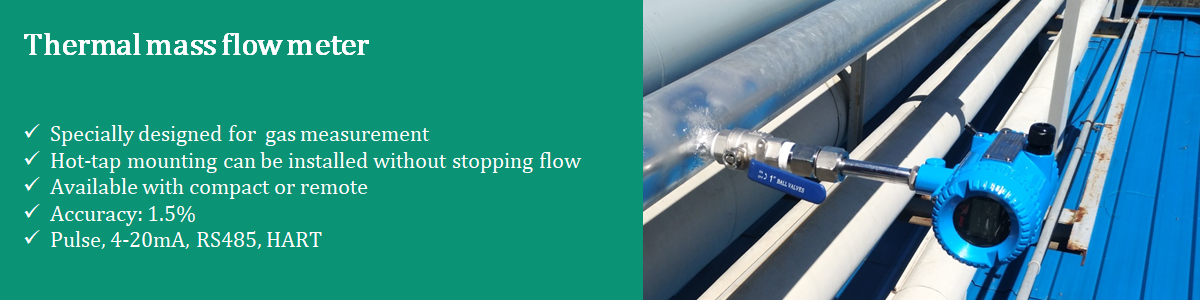
Installation requirements for coriolis mass flow meters
Views : 5024
Update time : 2017-03-13 11:07:00
1. Installation Position Selection
The flowmeter should be placed away from interference sources (such as a pump), which may cause vibration in the pipe. If the flowmeters are used in series along the same line, care must be taken to avoid the mutual influence due to vibration resonance. The distance between sensors should be more than 2 m.When installing the sensor, pay attention to the expansion and contraction of the process pipeline due to temperature changes. It is strongly recommended that the sensor not be installed near an expansion joint of the process pipeline. Otherwise, the pipe expansion and contraction of the pipeline will cause transverse stress, which will affect the flowmeter’s zero and will affect the measurement accuracy.
The flowmeter should be placed at least 5 m away from industrial electromagnetic interference sources, such as large power motors and transformers.
The sensor should be placed in the position where its measuring tube is always filled with fluid and pressure is maintained at the outlet, thus it should be placed in a position lower than the pipeline.
MEGACF does not require straight pipe upstream or downstream. However, if more than one mass flow transmitters are installed in the same pipe, ensure the length of pipe between any two flowmeters is more than 2 meters.
2. Closing of Valve Before zero-point Calibration
It is necessary to do zero-point calibration after the installation is completed. Close the downstream stop valve before zero-point calibration, and then close the upstream stop valve.3. Installation Direction
The MEGACF should be installed to ensure the measuring tube is filled with the medium being measured.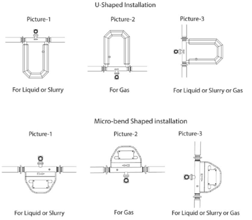
For horizontal installation, the measuring tube should be installed downside of the pipeline when the process medium is liquid or slurry (Picture 1); upside of the pipeline when the process medium is gas (Picture 2). For vertical installation, the measuring tube should be installed besides the pipeline when the process medium is liquid or slurry or gas (Picture 3).
4. Difficult Installation Location for Liquid and Gas Measurement
The flowmeter must not be mounted at the highest point of the tubing (A) if gas bubbles are expected, or at the lowest point (B) if solid particles are expected. Also, the meters must not be mounted in a drop-line near the open end (C), to avoid the flowmeter becoming empty.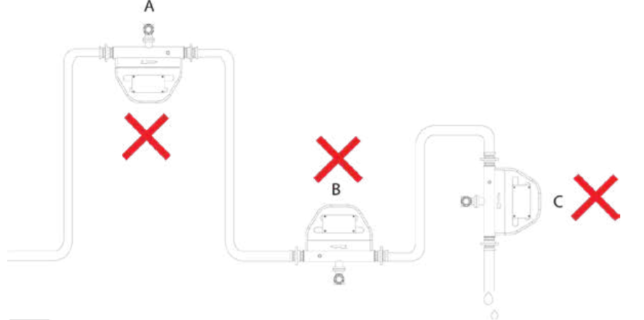
• Pipe reduction or extension should be avoided directly before or after the flowmeter
• Avoid any control valves, or orifices, or any sound generator near the sensor
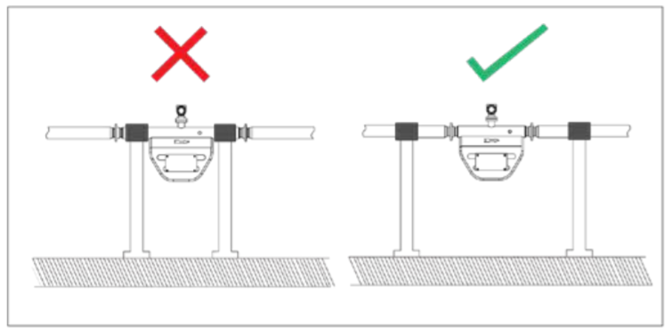

Avoid direct installation at the sensor side as this can cause measurement errors. For installing 6” or larger size flowmeter, support the sensors using the rubber connectors as the buffer.

5. Flow Direction

The flow arrow in front of the flowmeter indicates the direction of flow, so install the MEGACF accordingly. Otherwise, the transmitter may not display the mass flow accurately. If the process medium is liquid or slurry, the flow direction is downto-up; if the process medium is gas, the flow direction can be either down-to-up or up-to-down.