

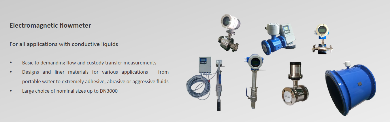
MEGAMF5000 Series is a kind of battery powered electromagnetic converter. This electromagnetic converter is capable of being used together with common electromagnetic flow meter sensor, with the flow rate measurement accuracy up to 0.5 level.
MEGAMF5000 Series battery powered electromagnetic converter has a lithium battery, which is capable of working 3 to 6 years consecutively.
Looking for more information on our people,
technology and solutions?
Contact us: sales@mega-meter.com
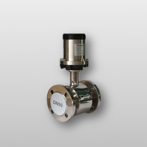
| Sizes | 6-800mm |
| Measuring Range | 0.1-15m/s |
| Temperature | -20~+60℃ (Neoprene) -20~+120℃ (PTFE) -40~+140℃ (FEP) -10~+60℃ (Polyurethane) -40~+180℃ (PFA) |
| Process Connection | Flange, Wafer, Thread, Tri-clamp |
| Accuracy | ±0.5% |
| Liner | Polyurethane, Neoprene, FEP, PTFE, PFA |
| Flange Types | ANSI, DIN, JIS |
| Material | SS #201/304 flow tube, carbon steel flanges & coil housing, powder coated aluminum electrical enclosure |
| Conductivity | must be ≥ 5 µS/cm |
| Electrode & Grounding | Stainless Steel #316L / Hastelloy B / Hastelloy C / Titanium / Tantalum / Platinum -iridium alloy |
| Display | Flow rate, flow velocity, percentage, Total flow |
| Grounding Resistance | Must be less then 10 Ω |
| Protection | IP 68 |
| Ambient Tempearture | -20~60 °C |
| Cable entry | M20x1.5 |
| Max rated pressure | 35MPa |