
Vortex Flowmeter Principle
A vortex flowmeter primarily consists of a bluff body, a sensor assembly and a transmitter. A bluff body or a shedder is nothing but a non-streamlined object or a barrier placed perpendicular to the axis of the pipeline, around which the medium flows. The frequency of the vortices, i.e. the number of vortices shed per second, is directly proportional to the velocity of the medium. This vortex shedding frequency is used to calculate the mass flow. The sensor assembly records the pressure and velocity oscillations generated on each side of the bluff body by the vortices and generates a digital linear output signal. The vortex shedding frequency is calculated using the following formula:
d
Where:
f = Frequency of vortex shedding
St = Strouhal number
V = Flow velocity
d = Width of the bluff body
Strouhal Number, St
The Strouhal number in the above formula is also known as “reduced frequency”. It is a dimensionless parameter which is a measure of the vortex shedding frequency and the velocity of the flow medium. It is calculated using the formula:
U
Where:
f = Frequency of vortex shedding
d = Width of the bluff body
U = Velocity of the flow medium
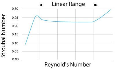
The Strouhal number is a function of the Reynold’s number. Reynold’s number is also a dimensionless parameter which is used to determine how the flow pattern of different fluids will change. The Strouhal number should remain constant when the Reynold’s number ranges from 2×10⁴ to 7×10⁶.
Calculation of volume flow rate
When the vortex shedding frequency is known, the volumetric flow rate can be calculated using the formula:
q = f*d/k
Where:
q = Volumetric flow rate
f = Vortex shedding frequency
k = k factor, which is a ratio of the pulses transmitted to the unit volume
Depending on the mounting style, the types of vortex flowmeters include:
Wafer type inline flowmeter |
This type of flowmeter is used for pipes with a diameter of four inches or less. It is mounted between two flanges by means of non-threaded holes through which bolts are inserted, tightened and sealed with washers, nuts, and gaskets. To ensure accurate readings, the meter is positioned such that its internal diameter is at the center with respect to the internal diameter of the pipeline. |
Flange type inline flowmeter |
A flanged-style flowmeter has flanged ends which are connected directly to the mating flange of the pipeline using bolts, nuts, and gaskets. |